Digital Electronics स
We know there are two types of signals, one is analog or continuous signal and the second one is Digital or discrete signal. So the science or field of research in the area of engineering is termed as Analog and Digital Electronics respectively. Now coming to the area of Digital Electronics, it is essential to understand wide range of applications from industrial electronics to the fields of communication, from micro embedded systems to military equipment. The main and perhaps the most revolutionary advantage of digital electronics is the decrease in size and the improvement in technology.This link is served by us. You do not need to download the graphic. Just highlight and copy the HTML code provided below, then paste it into the code for your Web site
We have chosen to discuss various topics of Digital Electronics from the very fundamentals of this subject such as Number systems, logic circuits going deep into those topics, like discussing various types of number systems, which we should use and how, inter relation among those number systems to the somewhat tougher concepts of Digital Electronics like TTL, PMOS-NMOS logic, Flip Flops etc. to get an idea about the whole subject.
All the topics of the related articles have been amply presented by diagrams, designs, tables and examples to make every topic understandable as much as possible. The topics are written in such a manner that if one go through them he will grasp the very basic idea at first attempt and further reading will enhance the technical knowledge.
Now let us inform you what we have included in the topics of Digital Electronics, as we have already discussed we have started from the very basic topics of Digital Electronics like Number system. Then we have discussed the extension of number system like various types of number system, interrelation among different types of number systems making oneself absolutely comfortable with the fundamentals of Number system. Then we have enlightened the very important field of Digital Electronics i.e. Binary Arithmetic and Boolean algebra. And we have discussed about them in elaborated manner. From binary addition, binary subtraction, binary multiplication and binary division to the basics of Boolean algebra.
After that we have written topics about various types of codes such as ASCII code, Gray Code, Hamming code which have made the input output format very easy. Then various types of logic gates (AND gate, OR gate, NOT gate, NAND gate, NOR gate, EX-OR gate) have been discussed in an elaborated manner with diagrams, explanations and truth tables to make each one of them very easy to understand.
These may be classified as the fundamentals of Digital Electronics without which the subject cannot be understood at all. So after discussing about them we have gone deep into the subject. Topics like TTL, Logic Families, various MOS gates, Flip Flops (J-K, D, T etc.) have been discussed.This link is served by us. You do not need to download the graphic. Just highlight and copy the HTML code provided below, then paste it into the code for your Web site
The sole purpose of introducing this subject in our Electrical Engineering website is because now days all the engineering streams are interrelated and the knowledge of Digital Electronics is very much essential for an electrical Engineer and we have tried our best to make oneself familiar with the subject technically as much as possible.
All the topics of the related articles have been amply presented by diagrams, designs, tables and examples to make every topic understandable as much as possible. The topics are written in such a manner that if one go through them he will grasp the very basic idea at first attempt and further reading will enhance the technical knowledge.
Now let us inform you what we have included in the topics of Digital Electronics, as we have already discussed we have started from the very basic topics of Digital Electronics like Number system. Then we have discussed the extension of number system like various types of number system, interrelation among different types of number systems making oneself absolutely comfortable with the fundamentals of Number system. Then we have enlightened the very important field of Digital Electronics i.e. Binary Arithmetic and Boolean algebra. And we have discussed about them in elaborated manner. From binary addition, binary subtraction, binary multiplication and binary division to the basics of Boolean algebra.
After that we have written topics about various types of codes such as ASCII code, Gray Code, Hamming code which have made the input output format very easy. Then various types of logic gates (AND gate, OR gate, NOT gate, NAND gate, NOR gate, EX-OR gate) have been discussed in an elaborated manner with diagrams, explanations and truth tables to make each one of them very easy to understand.
These may be classified as the fundamentals of Digital Electronics without which the subject cannot be understood at all. So after discussing about them we have gone deep into the subject. Topics like TTL, Logic Families, various MOS gates, Flip Flops (J-K, D, T etc.) have been discussed.This link is served by us. You do not need to download the graphic. Just highlight and copy the HTML code provided below, then paste it into the code for your Web site
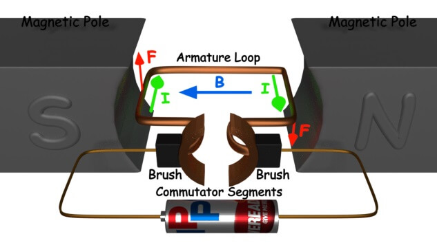 The very basic
 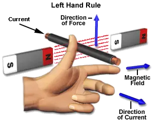 If a current carrying
  We know that when an infinitely small charge dq is made to flow at a velocity ‘v’ under the influence of an
 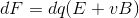 For the operation of DC motor, considering E = 0
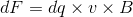 i.e. it’s the cross product of dq v and magnetic field B.
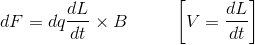 Where, dL is the length of the conductor carrying charge q.
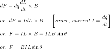 From the 1st diagram we can see that the construction of a DC motor is such that the direction of current through the armature conductor at all instance is perpendicular to the field. Hence the force acts on the armature conductor in the direction perpendicular to the both uniform field and current is constant.
 So if we take the current in the left hand side of the armature conductor to be I, and current at right hand side of the armature conductor to be -I, because they are flowing in the opposite direction with respect to each other.
 Similarly force on the right hand side conductor
 Therefore, we can see that at that position the force on either side is equal in magnitude but opposite in direction. And since the two conductors are separated by some distance w = width of the armature turn, the two opposite forces produces a rotational force or a torque that results in the rotation of the armature conductor.
 Where, α (alpha) is the angle between the plane of the armature turn and the plane of reference or the initial position of the armature which is here along the direction of magnetic field.
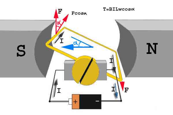
 Since, α = 0, the term cos α = 1, or the maximum value, hence torque at this position is maximum given by τ = BILw. This high starting torque helps in overcoming the initial inertia of rest of the armature and sets it into rotation.
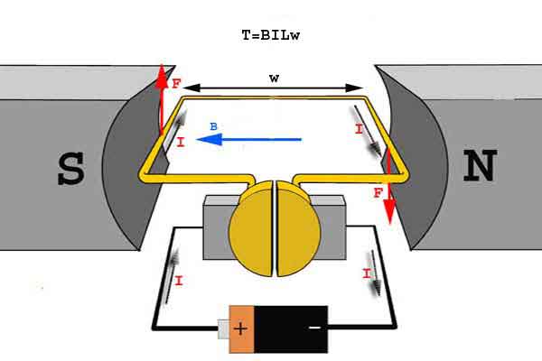


 i.e. virtually no rotating torque acts on the armature at this instance. But still the armature does not come to a standstill, this is because of the fact that the operation of DC motor has been engineered in such a way that the inertia of motion at this point is just enough to overcome this point of null torque. Once the rotor crosses over this position the angle between the actual position of the armature and the initial plane again decreases and torque starts acting on it again.

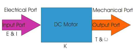 Here in a DC motor, the supply
  So from the picture above we can well understand that motor is just the opposite phenomena of a DC generator, and we can derive both motoring and generating operation from the same machine by simply reversing the ports.
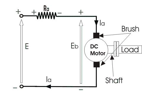

 Here,
Here,
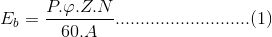
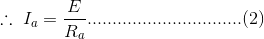
 Hence, speed of a DC motor is directly proportional to emf of rotation (E) and inversely proportional to
  Similarly, percentage (%) speed regulation is given as,
 Where,
 Therefore,
 A motor which has nearly constant speed at all load below full rated load, have good speed regulation.
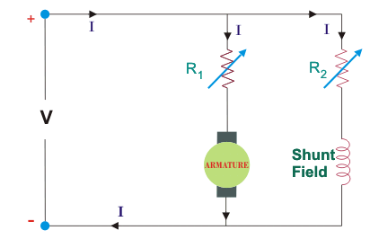
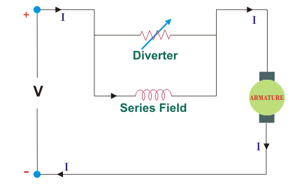
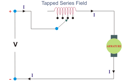
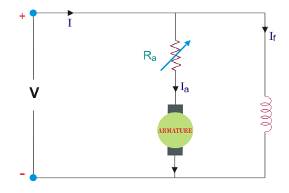 The power loss in the control resistance of DC series motor can be neglected because this control method is utilized for a large portion of time for reducing the speed under light load condition. This method of speed control is most economical for constant torque. This method of speed control is employed for